Integration with Raspberry Pi5 : rp1-cfe
cam-epc670 utilizes Raspberry Pi - Image Processing Signal Processor (PiSP) to interract with the host device.
The Raspberry Pi PiSP Camera Front End (rp1-cfe) driver is located under
drivers/media/platform/raspberrypi/rp1-cfe. It uses the V4L2 API to register a number of video capture and output devices, the V4L2 subdev API to register subdevices for the CSI-2 received and the FE that connects the video devices in a single media graph realized using the Media Controller (MC) API.
Follow the kernel page for details of PiSP: https://docs.kernel.org/admin-guide/media/raspberrypi-rp1-cfe.html
Follow the draft datasheet for details: https://datasheets.raspberrypi.com/camera/raspberry-pi-image-signal-processor-specification.pdf
Data Flow
In this setup with RPi5 with PiSP we basically have:
Component |
Role |
|---|---|
epc670 |
Generates RAW images with timing, exposure, gain. |
CSI-2 |
Converts CSI-2 packets into pixel words; feeds them reliably into the user space |
Memory outputs |
V4L2 buffers where frames land for user space |
We can think data flow as follows:
[epc670] -> [CSI-2] -> [memory outputs]
Note that further video processing pipelines interface with /dev/video0 and the data does not flow through PiSP FE-BE.
Media Topology
The media topology registered by the rp1-cfe driver is as follows.
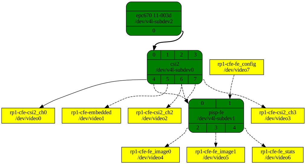
Follow steps below to regenerate the figure
Using media-ctl to get the media topology
To graphically view the media topology from the terminal, you can use the media-ctl tool together with Graphviz.
Install the required tools
sudo apt install v4l-utils graphviz
Find the valid media device
Run
v4l2-ctl --list-devices
and note the one which is listed under rp1-cfe (platform:1f00128000.csi)
You can also use
docker/scripts/media_device.sh. Check the script for details.
Dump the media topology in DOT format
Replace the name <media-device> with the media device you see in step 2.
media-ctl -d <media-device> --print-dot > topology.dot
Render the graph as an image
# Save to svg
dot -Tsvg topology.dot -o topology.svg
# Save to png
dot -Tpng topology.dot -o topology.png