Hardware Description
The hardware components of the epc670 ToF HAT+ are described here.
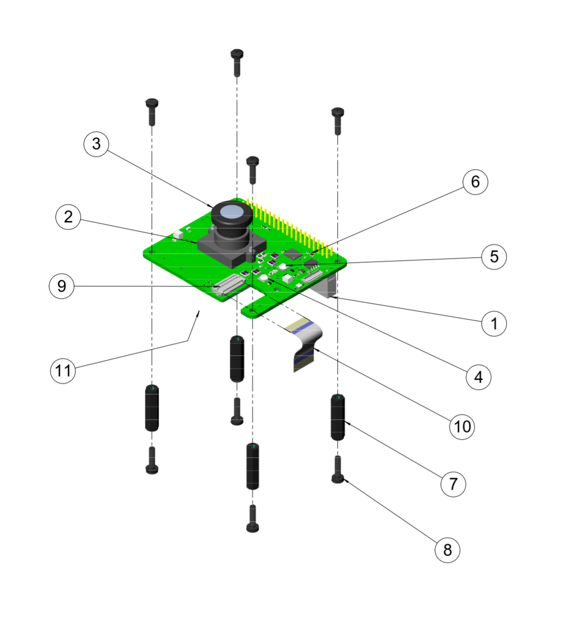
Components
Item |
Name |
Description |
|---|---|---|
1 |
Standard Rasperry Pi Pin Header compatible providing power to the HAT |
|
2 |
Lens holder |
Lens Holder M12x0.5 10mm with 940 Bandpass Filter |
3 |
Lens |
Lens 149° FOV, M12x0.5 thread |
4 |
Illumination LED 1 |
Infrared LED, λ=940nm, 2θ=150° |
5 |
Illumination LED 2 |
Infrared LED, λ=940nm, 2θ=80° |
6 |
Status LED |
Red LED for status information |
7 |
Standoff |
M2.5 Standoff 10mm Female-Female |
8 |
Screw |
M2.5 Screw |
9 |
FFC Connector 22-pin, 0.5mm pitch |
|
10 |
FFC Ribbon |
FFC Ribbon 22-pin, 0.5mm pitch, 30 mm length |
11 |
Clock Gen |
Clock Generator Si5351ABGTR with 25 MHz input clock crystal |
Header 40-Pin
Pins which are not included in this list match the general Raspberry Pi GPIO Pinout and have no purpose for the epc670 ToF HAT+.
Pins |
RP GPIO |
Name* |
Description |
|---|---|---|---|
1 |
- |
3V3 |
3V3 Supplies for Clock Generator |
2, 4 |
- |
5V0 |
5V Supply for Sensor and Illumination |
3 |
GPIO2 |
SDA |
I^{2}c lane connecting to Clock Generator, Board Temperature Sensors |
5 |
GPIO3 |
SCL |
I^{2}c lane connecting to Clock Generator, Board Temperature Sensors |
6, 9, 14, 20, |
- |
GND |
All Grounds are shorted together |
7 |
GPIO4 |
EN_VDD_A |
Enable signal for 5V power domain for sensor |
8 |
GPIO14 |
EN_CLK_SUPPLY |
Enable signal for power for clock generator |
10 |
GPIO15 |
EN_VBS |
Enable -15V Backside Voltage |
11 |
GPIO17 |
EN_VDD_PLL |
Enable PLL 1.8V power domain |
12 |
GPIO18 |
EN_VDD_D |
Enable Digital 1.8V power domain |
13 |
GPIO27 |
SHUTTER |
Shutter signal |
15 |
GPIO22 |
RESET_B |
Reset signal |
18 |
GPIO24 |
EN_VDD_PXH |
Enable signal for PXH 10V Domain |
19 |
GPIO10 |
MOSI |
SPI lane to device EEPROM |
21 |
GPIO9 |
MISO |
SPI lane to device EEPROM |
22 |
GPIO25 |
EN_VDD_FD_RST |
Enable signal for FD-RST 9V Domain |
23 |
GPIO11 |
SCLK |
SPI lane to device EEPROM |
24 |
GPIO8 |
CS |
SPI lane to device EEPROM |
26 |
GPIO7 |
EN_VDD_SF |
Enable signal for SF 10V Domain |
27 |
- |
ID_SD |
I^{2}c lane connecting to auto detection EEPROM |
28 |
- |
ID_SC |
I^{2}c lane connecting to auto detection EEPROM |
29 |
GPIO5 |
EN_LED_2 |
Enable signal for illumination LED 2 |
31 |
GPIO6 |
EN_I2C_PU |
Enable I^{2}c pull-up for sensor I^{2}c |
32 |
GPIO12 |
EN_LED_1 |
Enable signal for illumination LED 1 |
33 |
GPIO13 |
FAN_PWN |
Not supported yet |
35 |
GPIO19 |
EN_15V |
Enable signal for 15V Domain |
36 |
GPIO16 |
STATUS_LED |
Enable status LED |
37 |
GPIO26 |
ID_WP |
Write protection signal for auto detection EEPROM |
38 |
GPIO20 |
FAN_FEEDBACK |
Not supported yet |
40 |
GPIO21 |
EN_LED_EXT |
Not supported yet |
FFC connector 22-Pin
The 22-Pin FFC connector on the epc670 ToF HAT+ is used as the MIPI connector. To open/close use the black latch by flipping it (down-closed, orthogonal-open).
Pin |
Name |
Desription |
|---|---|---|
1 |
3V3 |
Not connected |
2 |
CAM_I2C_SDA |
I2^c Lane going to sensor, pulled up when EN_I2C_PU (Header) is active |
3 |
CAM_I2C_SCL |
I2^c Lane going to sensor, pulled up when EN_I2C_PU (Header) is active |
4, 7, 10, 13, |
GND |
All Grounds are shorted together |
5 |
- |
Not connected |
6 |
- |
Not connected |
8 |
DATA_3_P |
MIPI data lane 3 non-inverted |
9 |
DATA_3_N |
MIPI data lane 3 inverted |
11 |
DATA_2_P |
MIPI data lane 2 non-inverted |
12 |
DATA_2_N |
MIPI data lane 2 inverted |
14 |
DATA_CLK_P |
MIPI clock lane non-inverted |
15 |
DATA_CLK_N |
MIPI clock lane inverted |
17 |
DATA_1_P |
MIPI data lane 1 non-inverted |
18 |
DATA_1_N |
MIPI data lane 1 inverted |
20 |
DATA_0_P |
MIPI data lane 0 non-inverted |
21 |
DATA_0_N |
MIPI data lane 0 inverted |
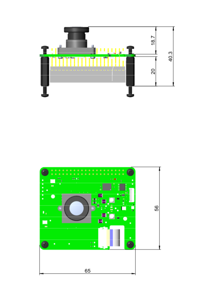
Dimensions